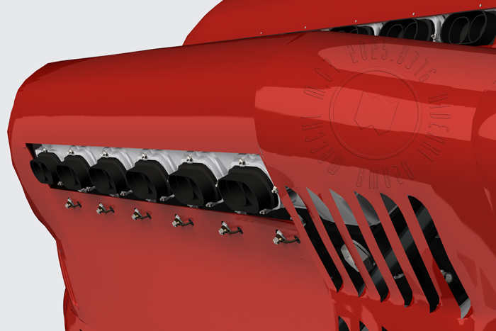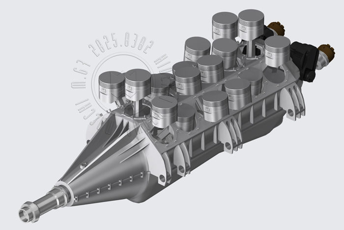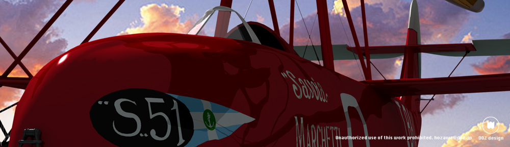
I guess the overall exterior is mostly done… setting aside the finer details.
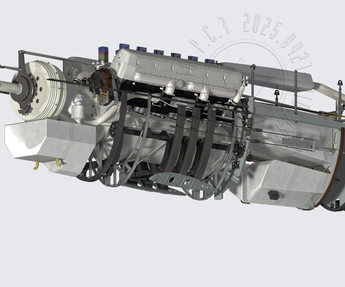
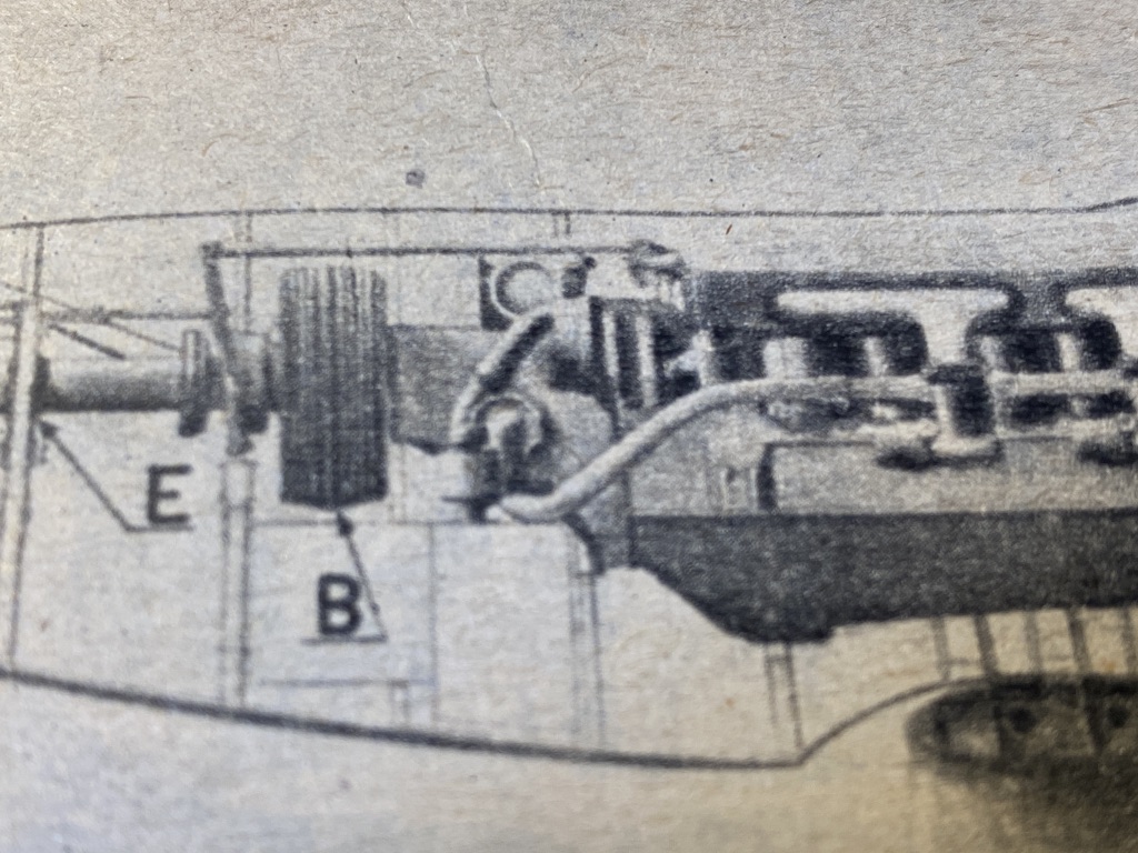
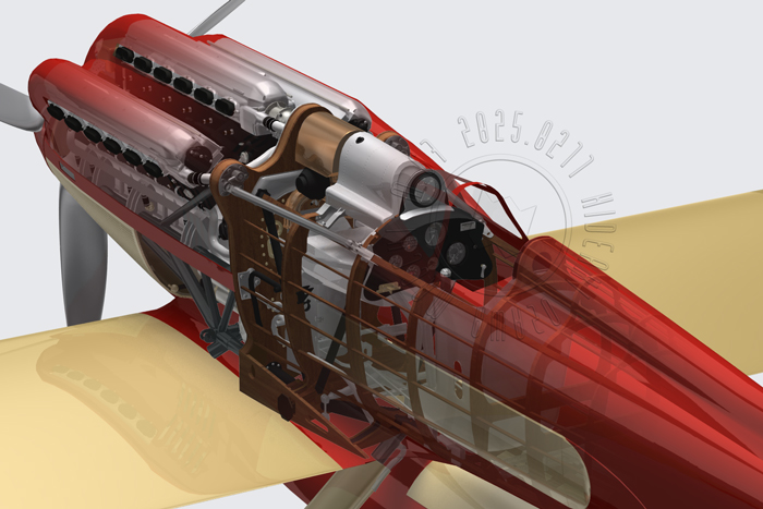
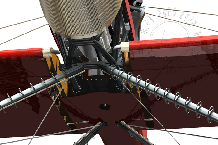
No decent references for the cooling or fuel lines, so it’s all mostly guesswork at this point—but I do want to hook up whatever looks like it ought to connect.
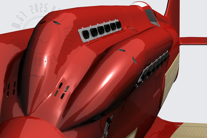
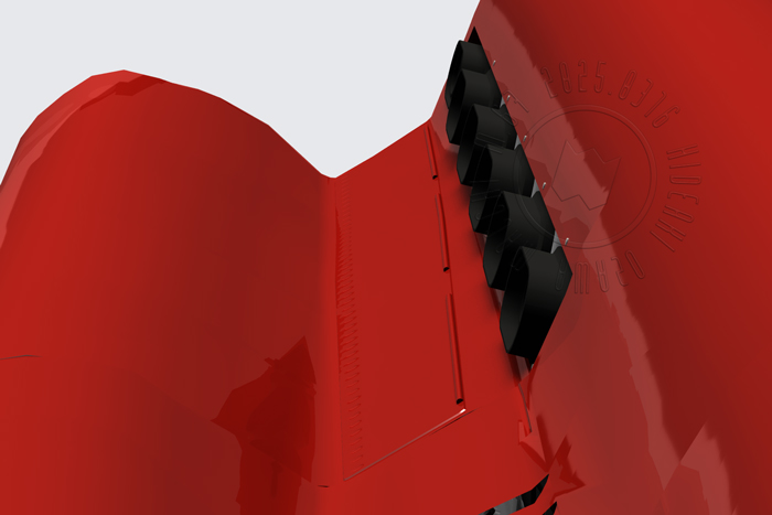
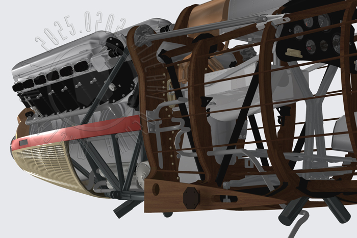
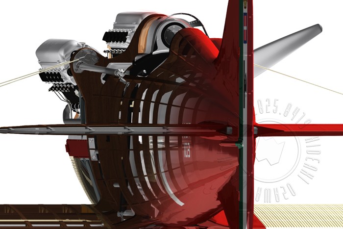
…aaaaand I forgot to render the wing-skin radiators. Brilliant. Just brilliant.![]()
細かいディテールを除けば外観が一通りできたかな…冷却系や燃料系のパイプ回りの資料も無いのでほとんど推測になるけれど、つなぐべきものはつなぎたい。
あ、翼面のラジエータ、レンダリング忘れた w